
Exploring Contactors - Your Essential Guide
So, what is a Contactor?
Ever wondered what makes electrical systems tick? Enter the contactor—a nifty device that's all about switching circuits, on and off using an electromagnetic coil to open and close a set of contacts, resulting in a circuit powering on or off. Contactors are used in applications where higher currents need to be switched. You can rightly consider contactors as high-power relays.
What are Contactors Used for?
A contactor is used in applications where there is a need to switch power on or off, frequently and rapidly. Contactors are designed, and built to perform this task reliably with a long life span, millions of cycles can be achieved.
A contactor can be configured either, to power on a circuit when activated using normally open contacts, or to shut down power to a circuit when activated using normally closed contacts. Typical applications for a contactor are as an electric motor starter and lighting control systems.
A contactor can be optioned with additional safety features, such as power-cutoff, short circuit protection, overload protection, and under-voltage protection.
Since contactors are intended for higher power applications, they are physically larger and more robust than standard relay devices.
How Do Contactors Work?
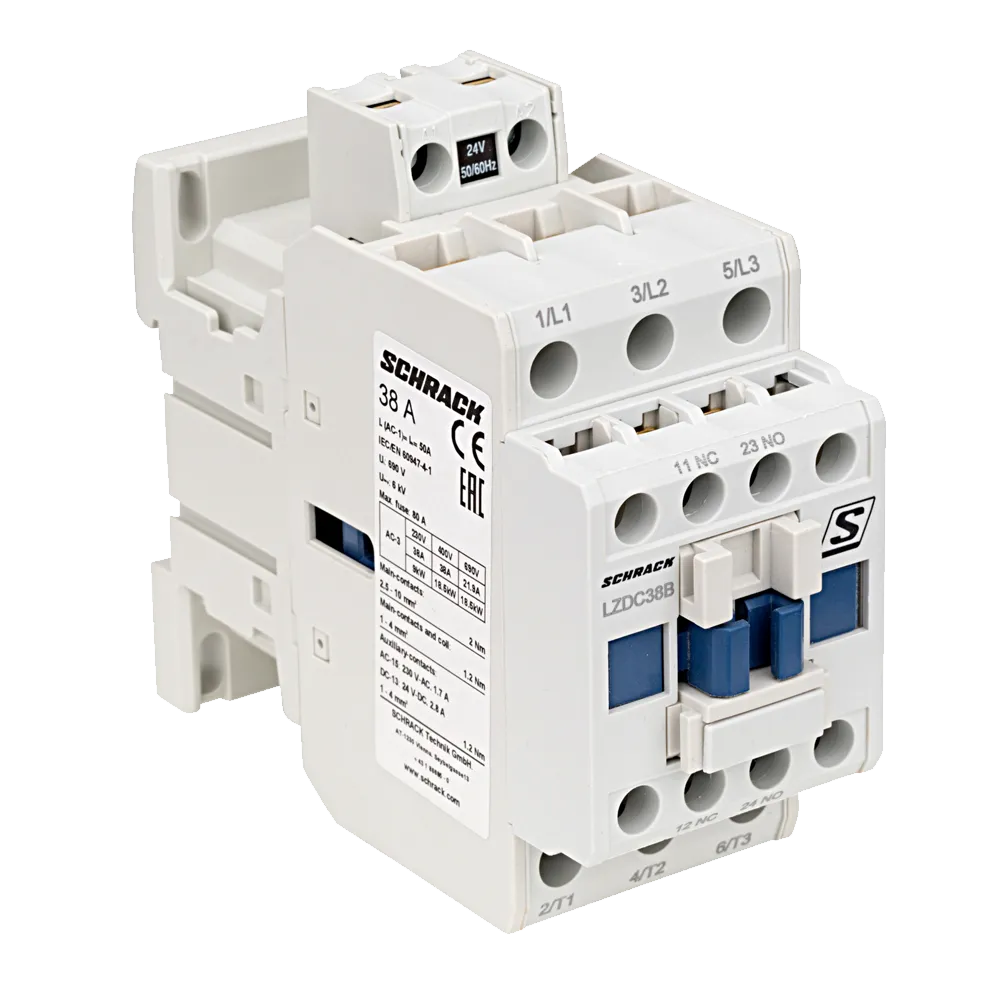
There are three core parts of any electrical contactor. These are the coil, the contacts, and the frame.
The coil, or electromagnet, is the key component; it will open or close the switch contacts when it is energised.
The contacts are what carries power across the circuit being switched. There are various types of contacts found in most contactors. Each type performs a specific function in activating the contactor, transferring power and providing feedback.
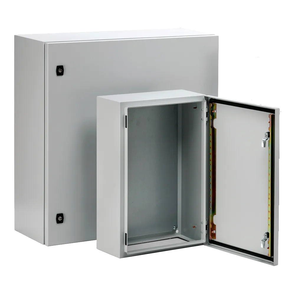
The contactor frame is the housing that holds it all together, protects the contactor’s components, and allows the contactor to be mounted. The frame protects users against accidentally touching any conductive parts , as well as offering robust protection against overheating, explosion, and environmental hazards like dirt and moisture ingress. Contactors come in different frame sizes based on their switching capacity.
The operating principle of an electrical contactor is; when the electromagnetic coil has a current passed through it, a magnetic field is created. This causes the armature within the contactor to close and, either open, or close the electrical contacts.
If the contactor is designed as normally open (NO), energising the coil with voltage will close the contacts together, and allow power to flow around the circuit. When the coil is de-energised, the contacts will open, and the circuit will open. This is how most contactors are used. A normally closed (NC) contactor works the opposite way. The circuit is made when the contactor is de-energised.
As contactors operate entirely via electromagnetism, it is one of the more efficient and reliable designs since electromagnetic switching only requires a small amount of power. It also enables the full remote operation of the contactor.
What's the Difference Between Contactors and Relays
The key differences between a contactor and a relay are:
Contactors are designed and built to handle much higher power switching applications than control relays. Relays are typically reserved for use with loads of around 5A-15A, and they are most often rated for 10A or less
Contactors are almost always set up in a normally open configuration. This means that the circuit will only be established when the coil is energised. Relays are typically configured with both normally open and normally closed contacts
Contactors being designed for high power applications offer a wide range of safety cut-offs and protections. Indeed, a specific type of safety switch known as thermal overload is used for preventing machinery and power circuits from overheating.
Other standard contactor safety features include:
Spring-loaded contacts, for interrupting an electrical circuit if the contactor is powered off
Overload protection that kicks in if the circuit receives a current surge for a defined period
Magnetic arc suppression, forcing any current arcs to travel a greater distance than the energy they carry can sustain
Contactors are physically bigger and heavier than relays, and their switching speed is considerably slower. They are also more expensive than relays in most cases and consume more power due to their larger electromagnetic coils.
What type of Contactors are available?
Contactors are available are available in single-phase and three-phase formats. Choosing the best electrical contactor for a given application involves careful assessment of various important criteria, features, and specifications. Load requirements and power ratings (voltage and current) will always be among the most crucial considerations, as will be what control voltage is used to energise the coil.
There are three common types of contactors, each can be seen by clicking on the type
Switching and Coil Ratings
Contactor switch ratings are usually; maximum switching voltage and maximum switching current. The upper limits of both voltage, and current must always be directly assessed in terms of the requirements for the circuit, or motor where it is being used.
While a product may be listed as a 230V contactor, 240V contactor, or 1000V DC contactor, more detailed manufacturer specifications will usually make direct reference to the maximum coil voltage, contact current rating, contact voltage rating, and overall power rating of a device. They will also list the number of auxiliary contacts, terminal type, normal state configuration, and minimum and maximum operating temperatures. Contactors generate more heat than relays, and this must be factored in when choosing a suitable unit for installation.
Various electrical ratings for contactors will often be given as either resistive AC-1, or inductive AC-3, depending on the intended use of the contactor. Resistive ratings are more common for contactors being used with heating elements, or lighting control installations, whereas inductive load ratings tend to be more common for motors, transformers, and solenoids.
AC-1 - This category applies to resistive loads, (non-inductive) or slightly inductive loads where the power factor is more than 0.95. Breaking the arc remains easy with minimal arcing and contact wear.
AC-3 - This category applies to high inductive loads, such as a squirrel cage motor switching with breaking during normal running of the motor once it is up to speed. On closing of the contacts, the contactor is subjected to an inrush current, which can be 5 to 7 times the rated full load current of the motor. On opening, the contactor breaks the rated full load current of the motor. For this reason, the current rating is derated.
The contactor coil voltage (control circuit voltage) does not have to be the same as the load voltage being switched on and off. For example, the coil voltage could be 24VDC, but the motor being switched on and off could be 415VAC. Typical coil voltages available include 12, 24, 48, 110, 230, and 400V.
What is the most common reasons for Contactors to Fail?
There are several reasons why a contactor could fail. The most common is where a contact becomes stuck or fused in one position. This is typically a result of excessive inrush currents, unstable control voltages, too low transition times between high peak currents, or simply due to normal wear and tear. The latter usually manifests as a gradual burning off of the alloys coating the contact terminals, causing the exposed copper underneath to weld together.
A less common reason for a failing contactor is a coil failure, most often caused by an excessive (or insufficient) voltage at either end of the electromagnetic coil. Dirt, dust, or moisture ingress into the air gap around the coil can be a contributing factor.
What are the possible reasons for noise coming from a contactor?
Chatter, humming or buzzing coming from a contactor indicates a problem. There are three common issues that could cause unexpected noise from a contactor.
The control voltage supplying the coil is not in the acceptable range for the coil rating. Typically, coils are designed to operate between 85% and 110% of its rated voltage. To verify that the control voltage is aligned properly with the selected coil, the voltage should be measured at the coil terminals (A1/A2). Once the contactor that is being operated in the closed state, the drop-out voltage will be about 60% of the rated voltage. Excess heat is the main cause of shortening the life of a coil. Even though the coil can operate at 110% of its rated voltage, doing so for long periods may shorten coil life.
The control source is not providing the necessary current to pick up the coil. Operating coils for contactors and relays rely on current in the windings to produce enough magnetic flux to span the ‘air gap’. The air gap is the distance between the pole faces of the yoke and armature which is at a maximum distance when the device is open or OFF. Once energised the the yoke and armature start to come together, the air gap decreases and current demand decreases as well. The closed state results in zero air gap and the amount of current required to keep the pole faces together is at a minimum and is referred to as “closed current” or “sealed current” or “steady state current”. The amount of current required to pick-up and close an AC or DC controlled device can be calculated from the VA ratings for inrush and seal found in the specifications for that device. Simply divide the VA rating by the coil voltage to calculate the required ampere rating of the control source.
There is debris on the pole faces of the yoke and armature. Debris like plastic or metal shavings may make the device noisy and may cause the coil to draw more current than it is rated for. Oxidation and rust can appear on pole faces and cause noise, also. This is more likely to be seen in older devices or those used in high humidity or corrosive environments.