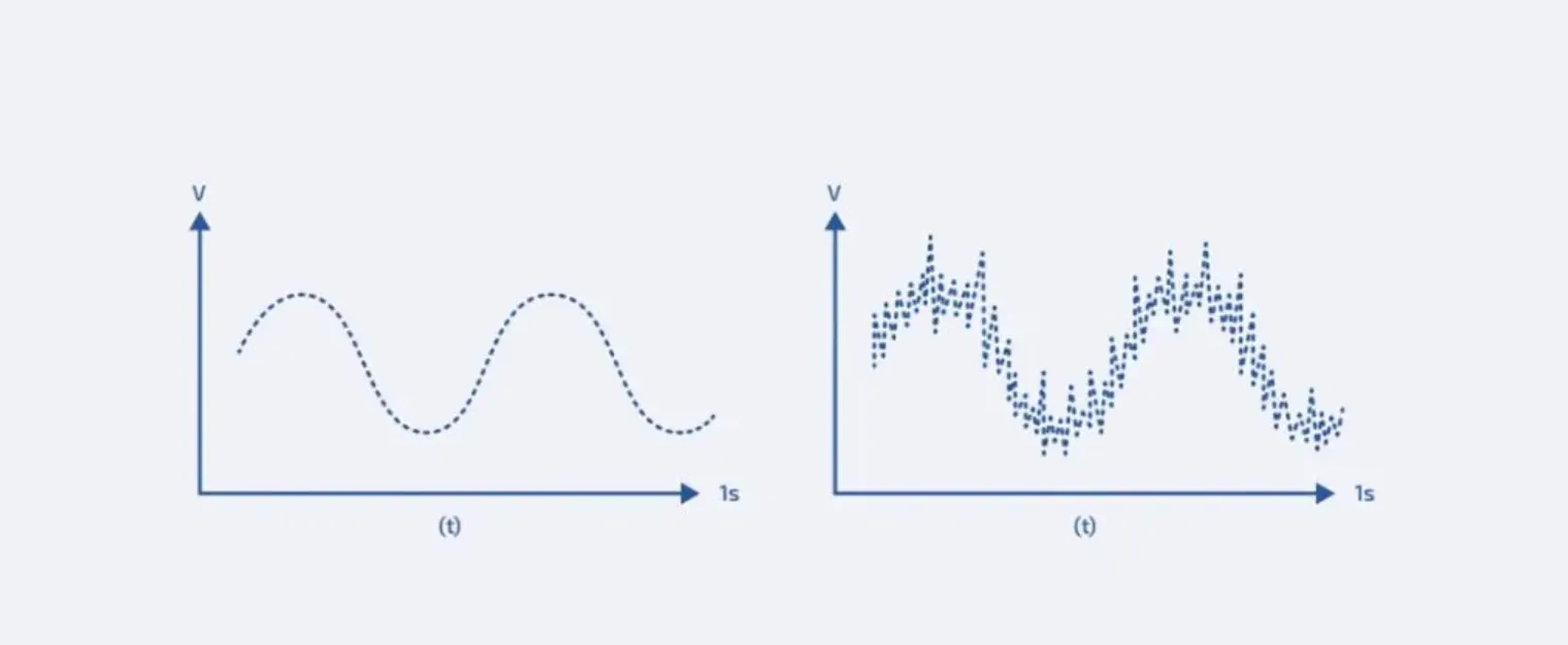
Variable-speed drives provide a series of advantages to their users, however, one of their main problems is that of EMI or Electro-Magnetic Interference. This can cause problems in the motor if not dealt with correctly. In order to limit the extent of EMI it is necessary to use the right equipment and a cable with EMC, or Electro-Magnetic Compatibility.
Cables for variable frequency motor drives EMC
The use of EMC variable frequency drive motors has been increasing, where they are gradually replacing traditional motor systems. But while this technology has great advantages, it does bring with it some drawbacks; these, however, can be mitigated or remedied.
Disturbances caused by the use of: Motors + Inverters
Three types of disturbances occur with the use of this equipment:
1. EMISSION OF HARMONIC FREQUENCY CURRENTS INTO THE GRID:
This can be avoided by following the recommendations of the equipment manufacturer. Depending on the size of the equipment, some of the manufacturers recommend placing harmonic filters on the power supply line, so as not to cause high-frequency disturbances to the network.
2. DAMAGE TO THE MOTOR AND ASSOCIATED DRIVE AS A RESULT OF HIGH FREQUENCY EDDY CURRENTS:
Damage to the motor and associated drives is the consequence of high-frequency currents inside the motor. The cause of the circulation of high-frequency currents inside the motor is the capacitance imbalance of the motor winding turns with respect to the stator; these imbalances allow the high-frequency currents to close through the stator iron and not continue into the copper winding.
This high-frequency stray current does not return to the inverter via the motor cable but via the shielding or earthing.
The effect is an induced voltage in the rotor which generates a current that follows one of the following paths: 1) rotor – bearing – stator – bearing – rotor or 2) rotor – coupled gears – ground – bearing – rotor.
3. EMISSION OF HIGH FREQUENCY ELECTROMAGNETIC WAVES:
This can be avoided by choosing properly screened cables, approved cable glands and proper shielding of boards and motors.

Leakage of electromagnetic waves at high frequencies occurs when even small gaps remain in the screen.
Electro-Magnetic Compatibility
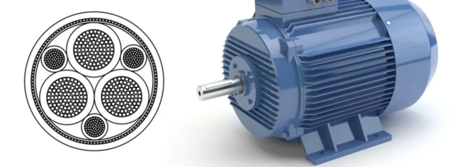
With regards to cable the necessary EMC screening is achieved by firstly, ensuring a symmetrical distribution of the conductors. This is achieved by splitting and reducing the earth conductor to fit snugly into the gaps between the conductors. Secondly, a special protective screen is added to ensure the required EMC when variable-speed drives are used. The result of using the right cable means a longer lifespan for the motor.
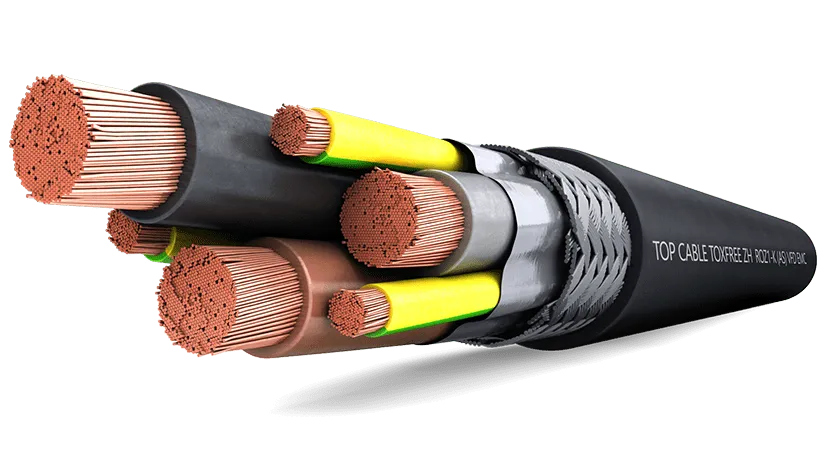
The cable manufactured by Top Cable provides the ideal design for drive cables offering high mechanical resistance and electro-magnetic compatibility (EMC) due to the 100% shield coverage.
DOUBLE SCREEN design (Top Cable brand):
Electro-Magnetic Compatibility
With regards to cable, the necessary EMC is achieved by firstly ensuring a symmetrical distribution of the conductors. This is achieved by splitting and reducing the earth conductor to fit snuggly into the gaps between the conductors. Secondly, a special protective screen is added to ensure the required EMC when variable-speed drives are used. The result of using the right cable means a longer lifespan for the motor or pump and less down time in the repair shop.
FAQ's about TOPDRIVE® ROZ1-K VFD Cable (EMC)
Are all VFD cables the same and what advantages does the TOPDRIVE® ROZ1-K cable have?
Top Cable’ s TOPDRIVE® ROZ1-K cable design is the one with the highest performance, favouring earth leakage and avoiding the effect of voltage peaks:
Flexible copper conductor (class 5), which gives the cable maximum flexibility.
Arrangement of conductors and earth three plus three (3C+3G) to avoid current leakage through earth.
Cross-linked polyethylene insulation (XLPE) with performance far superior to PVC.
Double aluminium-polyester screen that offers 100% shielding and thus prevents the emission of electromagnetic waves from our cable to the rest of the equipment.
Tinned copper braid, with anti-corrosion features and better installation.
Halogen-free outer sheath (LSHF) with the highest CPR classification (Cca – s1a, d1, a1) with low emission of fumes and corrosive gases in case of fire to protect people and equipment.
This is why Top Cable’s TOPDRIVE® R0Z1-K cable is recommended by leading manufacturers of variable frequency drives and also by GAMBICA, the British Capital Goods Association.
Can I install an unshielded cable to power motors with VFD drives?
A cable with an inadequate shield (or no shield) can act as an antenna and be a source of radiated emissions. Unshielded cables do not guarantee electromagnetic compatibility and impedance matching, and are therefore not suitable for powering VFD motors.
Similarly, it is not advisable to install single core cables, even if they are shielded, as it is necessary to compensate for inductions and respect the symmetrical configuration of the 3C+3G phases particularly in higher current applications.
How does a variable frequency drive (VFD) work?
A Variable Frequency Drive (VFD) is a system for controlling the rotational speed of an alternating current (AC) motor by controlling the power frequency supplied to the motor.
An electric motor rotates its rotor according to the parameters achieved by the voltage and frequency of the electrical power supplied to the motor. Internationally, there are different mains voltages, such as 400 V (three-phase), 380 V (three-phase), etc., and frequencies of 50 or 60 Hertz. By varying the voltage and/or frequency, the performance of the motor, including the speed, varies. It is usually difficult to change the voltage or frequency without auxiliary equipment.
To vary the voltage and frequency effectively, a variable frequency drive is used. Normal power is supplied to the VFD and the output of the VFD is fed to the electric motor. The VFD has controls that can be adjusted to control the speed of the motor.
A VFD provides precise control of the speed and torque of an AC motor through pulse width modulation (PWM). In a VFD system, it is critical to choose the right cable for best performance, maximum energy efficiency and long life.
What certifications does the TOPDRIVE® ROZ1-K cable meet? What is its CPR rating?
TOPDRIVE® R0Z1-K cable has been designed according to the IEC 60502-1 / IEC 60092-353 reference standard and complies with the European CPR (Construction Products Regulation) Cca – s1a, d1, a1. In addition, the TOPDRIVE® R0Z1-K cable is CE / UKCA / BUREAU VERITAS / DNV-GL / ABS /LLOYD’S REGISTER / RoHS /.
What features does the TOPDRIVE® ROZ1-K cable offer against fire?
Flame non-propagation according to UNE-EN 60332-1 / IEC 60332-1.
Fire non-propagation according to UNE-EN 60332-3 / IEC 60332-3 and EN 50399.
CPR reaction to fire: Cca-s1a, d1, a1, according to EN 50575.
Halogen-free according to UNE-EN 60754-1 / IEC 60754-1.
Low emission of corrosive gases according to UNE-EN 60754-2 / IEC 60754-2.
Low smoke emission according to UNE-EN 61034 / IEC 61034:
Light transmittance > 80%.
What is the colour code of the TOPDRIVE® ROZ1-K cable?
The standardised identification of the insulated conductors of the TOPDRIVE® R0Z1-K cable is as follows:
3 x + 3 G: Grey + brown + black + Yellow/Green (3G) (from 6 mm2).
4 G : Grey + brown + black + Yellow/Green (up to 4 mm2).
What precautions should be taken into account during the installation of a TOPDRIVE® ROZ1-K cable for VFD applications?
Certain precautions must be taken during installation:
Always respect the bending radius of the cable. Radii smaller than the minimum indicated may cause damage or breakage to the outer sheath.
Adequacy of the laying. The cable must be laid carefully, taking care not to damage the cover in irregular areas, sharp edges, etc.
Fixings/Fastenings. Adapt the fixings so that the cable adopts a natural position in the laying to avoid stress concentration on the roof. Allow a certain degree of freedom of movement and avoid excessively tight cable ties.
Why is it recommended to use XLPE cables (as opposed to PVC) to power VFD motors?
To avoid voltage peaks, we should use a cable with XLPE insulation (90ºC) instead of one with PVC insulation (70ºC). In addition, the dielectric coefficient of XLPE (2.3) is much lower than that of PVC (7.4), which also reduces the capacitive effect and therefore the magnitude of the reflected waves.

