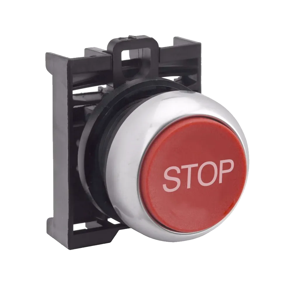

Switch Selection in Industrial Environments: Small Differences, Long-Term Impact
Switches are rarely the most complex components in a control system. Yet in higher duty environments, small differences in construction, actuation style and rating often determine whether a switch operates reliably for years or becomes an unexpected maintenance item.
Limit switches illustrate this clearly. The principle is straightforward. The operating conditions are not always.
Mechanical Life and Electrical Life Are Not the Same
Industrial limit switches are often rated for mechanical lives in the millions of operations. Figures such as 10 million mechanical cycles are common. Electrical life, however, is frequently lower and depends heavily on load conditions.
Mechanical life reflects the durability of the actuator and internal mechanism. Electrical life reflects the condition of the contacts under load. Switching inductive loads, managing inrush current or operating at higher frequencies can significantly influence contact wear.
For example, in conveyor applications where a limit switch may be triggered thousands of times per shift, the mechanical rating may appear generous. However, if the switch is repeatedly interrupting an inductive load without appropriate consideration, electrical wear can become the limiting factor long before the mechanical mechanism reaches its rated life.
Understanding both ratings independently is essential when predicting real service life.
Operating Frequency and Duty Cycle
Operating frequency is typically specified in activations per minute, but frequency alone does not capture the full mechanical picture.
Is the actuator engaged by a controlled cam profile, or does it experience abrupt impact at the end of travel?
Is there consistent overtravel beyond the operating point?
Is the switch mounted in a location subject to vibration?
In cam-driven packaging machinery, repeated side loading on lever actuators can accelerate fatigue even when operating frequency remains within nominal limits. Shock and misalignment introduce stresses that are not always obvious in specification tables.
Matching switch construction to actual motion conditions supports long-term mechanical stability.
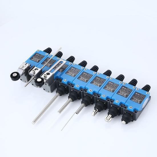
Actuator Geometry and Mechanical Loading
Actuator selection directly influences how mechanical load is transferred into the switch body.
Roller plungers, top plungers, roller levers, adjustable levers and rod styles each respond differently to force and alignment. The interaction between the moving target and the actuator determines how stress is introduced into the internal mechanism.
A plunger subjected to side loading may experience accelerated wear. Lever-style actuators can tolerate some misalignment but are subject to fatigue under continuous cycling. Adjustable designs provide installation flexibility, but alignment remains critical to avoid introducing unintended stress.
The geometry of the application, whether linear travel, rotary movement, cam actuation or edge detection, should guide actuator choice. Aligning actuator type with motion profile reduces mechanical stress and supports longer, more predictable service life.
Operating Force and Application Matching
Operating force varies significantly between switch types. Heavy-duty industrial limit switches may require actuation forces in the hundreds of grams. Micro switches operate at much lower forces.
In higher impact environments, such as end-of-travel detection on larger mechanical assemblies, specifying a micro switch may result in premature failure. Conversely, selecting a heavy-duty unit in a low-force application can introduce unnecessary mechanical resistance or design constraints.
Force should reflect the physical realities of the installation rather than simply dimensional fit.
Environmental Exposure Beyond IP Rating
Ingress protection is often the first environmental metric considered. Open types may be rated around IP40, enclosed units commonly IP65 and sealed designs IP67. These ratings provide guidance for dust and water resistance.
However, environmental exposure is broader than ingress alone.
Temperature variation, vibration, shock and potential chemical exposure all influence performance. In washdown environments or outdoor installations where temperature cycling is significant, material choice and sealing design become equally important considerations.
Plastic housings may be suitable for lower-frequency commercial applications. Aluminium bodies offer improved durability for industrial duty. Stainless steel may be preferable in particularly corrosive conditions.
Suitability is defined by the total operating environment, not a single rating.
Contact Configuration and Load Considerations
Limit switches are commonly available with normally open and normally closed contacts, often combined within a single unit. Double-pole configurations are also available where circuit requirements demand them.
Rated voltage and current, commonly up to 250 Vac at 5 A with heavier capacities available, must align with the control circuit. In applications switching higher inductive loads, realistic load assessment becomes part of responsible specification.
Contact configuration should reflect circuit behaviour, not only wiring layout.
Treating Switches as Specification Decisions
Limit switches are fundamental components used for position detection, control logic and safety interlocking. Because they are familiar components, they are often selected efficiently within a design process.
In stable, low-cycle environments that approach is typically sufficient. In higher duty, higher cycle or mechanically demanding applications, subtle differences in actuator design, material selection and load handling capability influence long-term reliability more than many expect.
The principle of operation is simple. The operating context rarely is.
Careful alignment between environment, duty cycle and electrical load reduces avoidable maintenance and supports consistent system performance over time.
We stock a wide range of industrial and micro limit switches suited to varied operating conditions. Correct alignment between switch design and application conditions supports long-term reliability.